博文

目前显示的是 六月, 2018的博文

Brief introduction of mineral processing

图片
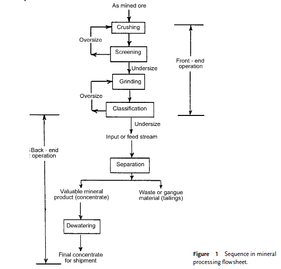
Mineral processing may be comprehensively described as the physical or chemical processing methods or their combinations, which may or may not lead to changes in the physical and/or chemical properties of a mined mineral resource, and which ultimately result in the production of a processed mineral product that can either be ready for use or be better suited for further processing. Mineral processing operations can be grouped into front-end and back-end operations as shown in Figure 1. The front-end operations essentially comprise processes leading to material severance and the back-end operations, to separation of the severed material into two parts – one that is valuable (called the concentrate), and the other that is not (called the tailings). Since most of the mineral processing operations are conducted wet, dewatering forms very much an integral part of the whole scheme. The content of the present chapter consists primarily of the two cited ends which best describe or convey qui

Mineral Processing Flowsheets

图片
In mineral processing plant , A general flowsheet involving almost all the unit operations pertinent to mineral processing is shown in Figure 1. The others refer specifically to beach sands, lead   zinc mining plant , molybdenum, and the rare earths . Processing of silica sands provides a good example of the response of minerals to magnetic and electrostatic fields. A generalized flowsheet for separating the mineral constituents of beach sands is shown in Figure 2 . It will be seen that the separation is essentially based on the differences in the magnetic properties and in the electrical conductivity of the various minerals present in the beach sands. The behaviour of some typical beach sand minerals, as for instance magnetite, ilmenite, garnet, monazite, rutile, zircon, and quartz , in respect of their responses towards magnetic and electrostatic separators. A reference is also drawn to Figure 3 which exclusively shows flotation playing the centrally important role in lead – z

Flotation system

图片
In beneficiation plant , Flotation, like all other separation processes, is imperfect in that simply by applying this process only once, very little separation may be achieved. For example, the underflow from a flotation machine unit may have many hydrophobic particles that have failed to encounter an air bubble, or the overflow may have hydrophilic particles that have simply been caught in the wake of an air bubble or in a collection of hydrophobic particles secured to a bubble. It is, therefore, common practice to operate many cells in complicated series – parallel arrangements, perhaps with adjustment of chemistry at some point. This is necessary because only a limited separation is usually attainable in a single device, and as such there is a need for roughing, cleaning, and scavenging components in a circuit. Generally speaking, roughing is the primary operation, which utilizes a moderate separating force to remove the fully liberated valuables. Scavenging utilizes strong che

DESIGN OF STORAGE SILOS AND HOPPERS

图片
In beneficiation plant , In the general field of bulk solids handling, ensuring that both the storage of materials and the movement from storage will be carried out in an effective and efficient manner is essential. However, the flow out of bins and hoppers is well known to be often unreliable; as a result, considerable costs are incurred because of consequential losses in production. Problems that commonly occur in storage bin operation include particle segregation, erratic feeding, flooding, arching, piping, and adhesion to the bin walls—all of which reduce the bin capacity below the values specified by the manufacturer. For example, a poorly flowing material may cause an arch or bridge over the hopper outlet or a stable rathole within the bin (see Figure 1). On the other hand, a very flowable material (dry, fine powder) may become aerated and subsequently fluidize, causing potential flooding problems. Where flow blockages occur in practice, a common response is to resort to flow

FILTRATION MACHINE- Batch and Semicontinuous Filters

图片
In beneficiation plant , Continuous filters tend to be more widely used in the mineral and coal processing field, particularly where large tonnages are involved. This preference reflects the lower capacities of batch or semicontinuous units and the increased labor requirements, both of which result in higher operating costs. However, at low-tonnage plants and under special conditions, these filters can have distinct advantages. Also, where pressure drops must be used that are higher than those obtained by continuous vacuum filters (because of the low cake permeability), the pressure filter may be applicable. For instance, tailings may be filtered to recover water or to dewater them to a high enough solids concentration to allow land disposal. The mineral and coal processing industry use batch and semicontinuous filters of four types: plate and frame filters, recessed plate filters, vertical disk pressure filters with or without sluice discharge, and automatic discharge plate and frame

FILTRATION MACHINE- Continuous Filters

图片
In beneficiation plant , filtration machine can be divided into three modes: continuous, batch and semicontinuous, and clarifying. Each of these modes can be further subdivided. The discussion that follows is limited to those units with significant application in mineral and coal processing . Continuous Filters Continuous filter s may be divided into those forming their filter cake against gravity and those forming their filter cake with gravity. Filters Forming Cake Against Gravity. Disk and drum filters all form cake against gravity. The latter can be further divided into scraper discharge, roller discharge, and continuous-belt drum filters. A disk-type filter contains a series of individual disks mounted on a center barrel. The barrel is held in trunion bearings mounted on either end of the filter tank. The disks are partially submerged in the feed slurry to a standard apparent submergence of about 35%. A higher submergence would require stuffing boxes around the center b

Thickeners

图片
In beneficiation plant , a conventional thickener consists of a circular tank with a central feedwell and peripheral weir overflow. Bottom slope will have a ratio of 1:12 up to 3:12 depending primarily on tank diameter and particle size distribution. For large-diameter units or for feeds containing a high percentage of coarser, fast-settling solids, a double slope is used. The inner third (approximately) of the diameter might have a 2:12 or 3:12 slope and the outer portion a 1:12 slope. (The use of rectangular and square tanks in coal processing is gradually decreasing.) Most thickeners will run at 0% – 20% of rated torque and as such will have a service life of 20 years or more. The great amount of extra torque is called into play in an upset condition (such as excessively coarse solids, underflow pump shutdown, excessive tonnages, or foreign object) to prevent a shutdown and the need to dig out the unit. The overflow is usually recycled back to processing for reuse. If it is to

Gravitational classifiers

图片
In mineral processing plant , Two basic types of gravitational classifiers employed today are the spiral classifiers and the rake classifier. They both introduce the feed submerged into a pool area and subject the solids to an upflow current. The overflow is obtained from a peripheral weir that provides the vertical velocity. A solid whose terminal settling velocity is high enough will settle against this current and report to the base of the pool. At this point, a rake or screw conveys the solids out of the pool and up the beach to drain the “sands” product before discharging it over the end of the slope. Figure 1 is a schematic of a spiral classifier. The rake classifier has a series of rakes (actually blades) that operate in a reciprocating fashion to move the sands up the beach. A third type is termed a “hydroseparator.” The feed again enters submerged through a circular centralized feedwell, and the peripheral overflow weir causes an upward velocity. The underflow is raked

Flotation column

图片
In mineral processing plant , The column flotation concept has been around for nearly 40 years, but it attracted attention with the lead-zinc mining  and iron ore processing problems of the early 1980s. The column flotation technique uses the countercurrent principle to improve separation by reducing entrapment of particles. A schematic diagram of column flotation cells is shown in Figure 8.53. The important operating difference from mechanical flotation cells is the lack of an impeller, or any other agitation mechanism, which reduces energy and maintenance costs. The other major difference is that for most ore-processing applications, wash water is sprayed into the froth at the top of the column, which is impossible to accomplish in a mechanical cell as it can kill the froth. The amount of wash water added is a major factor in determining flotation selectivity and recovery as well as column operation stability. In column flotation, the ore is fed into the column via a distribu

Flotation machines

图片
In mineral processing plant , Flotation machines are designed to ensure flow of the pulp into good, active contact of particles with bubbles and levitation of mineral-laden air bubbles to the top of the cell, allowing entrapped particles to be removed. In addition, some laboratory machines are also designed to allow study of the physicochemical principles involved in flotation subprocesses. Different attempts to meet these requirements have resulted in many designs. Essentially, flotation machines for production are divided into two types depending on the mechanisms by which air is introduced into the cell. Many variations of these types are seen, allowingdifferent intensity of agitation and different flow patterns in equipment with a variety of sizes and shapes. The two main types are pneumatic and mechanical machines. In pneumatic machines, air entering the turbulent pulp is dispersed into bubbles by baffles or perforated bases, ensuring maximum opportunity for contact with the m