DESIGN OF STORAGE SILOS AND HOPPERS
In beneficiation plant, In
the general field of bulk solids handling, ensuring that both the storage of
materials and the movement from storage will be carried out in an effective and
efficient manner is essential. However, the flow out of bins and hoppers is
well known to be often unreliable; as a result, considerable costs are incurred
because of consequential losses in production. Problems that commonly occur in
storage bin operation include particle segregation, erratic feeding, flooding,
arching, piping, and adhesion to the bin walls—all of which reduce the bin
capacity below the values specified by the manufacturer. For example, a poorly
flowing material may cause an arch or bridge over the hopper outlet or a stable
rathole within the bin (see Figure 1). On the other hand, a very flowable
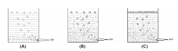
material (dry, fine powder) may become aerated and subsequently fluidize,
causing potential flooding problems.


Where
flow blockages occur in practice, a common response is to resort to
flow-promoting devices, which add to the expense of the installation and often
result in only a marginal improvement in reliability. In most cases, the
problems that occur in practice are caused by inadequate design analysis together
with a lack of knowledge of the relevant flow properties of the materials.
There are
basically three flow patterns in bins: mass flow, funnel flow, and expanded
flow (see Figure 2). Each of these flow patterns has its advantages and
disadvantages. Mass flow refers to a flow pattern where all the material in the
bin is in a downward motion whenever the feeder is discharging. In essence, the
material column slides along the hopper wall. To attain this type of flow pattern,
the hopper walls must be steep and smooth. Funnel flow occurs when the material
moves strictly within a confined channel above the hopper outlet. The material
outside this flow channel is at rest until the bin level drops and the material
slides into the channel. The diameter of this flow channel is established
essentially by the hopper outlet dimensions. However, when the cohesive
strength of the material is high enough, the flow channel may possibly be
emptied out without the upper layers in the bin sloughing off into the channel.
In this case, a continual open channel will be formed right within the bin.
Such a channel is referred to as a stable rathole (see Figure 1). Expanded flow
exhibits themass-flow pattern in the lower hopper section up to the point where
the stable rathole diameter is reached; then the flow pattern continues as
funnel flow. The stable rathole diameter can be calculated when the flow
properties are known.

Accurate
measurement of the flow properties is essential for proper design of the
storage bin and hopper. Once the shear tests have been completed, the values
for unconfined yield strength ( fc) can be plotted
in graphical form, as shown in Figure 11.4. The strength curves are referred to
as flow functions (FF). Figure 3 shows three flow functions: for low-, medium-,
and high-strength coals. (The lines marked 1.1, 1.2, and 1.3 represent flow
factors [ff], which represent stresses in different shapes of hoppers. The
intersection of FF and ff provides the critical value of the strength that is
used in computing the critical arching dimension.)
Once the
material strength is measured, the stresses within the granular material inside
the bin can be calculated. If any arching or doming situation can develop
inside the bin, the design engineer must make sure to create a geometric
configuration of the bin or hopper such that the stresses in the material (s) will be larger than the strength of the material ( f ). The basic flow criterion requires that f < s in order to
maintain gravity flow.
Figure 4
shows a typical graphical illustration of the pressure (p), strength, and stress distributions inside a bin and
hopper. The bulk solid is unconsolidated at the top of the bin because p is about zero. While the bulk solid is flowing downward,
it becomes consolidated under pressure p. For each value of pressure, corresponding values exist for the material
strength and stress. Close to the apex of the hopper, the f-curve and s-curve intersect. Above this point, the flow criterion f < s is satisfied
and gravity flow will occur. Below this intersection, we have f > s and arching
will occur. Therefore, this intersection identifies the critical level in the
hopper and also fixes the critical opening dimension (B). A thorough engineering analysis, based on the flow
functions shown in Figure 11.4, would show that the critical arching diameters
for a stainless steel-lined, conical mass-flow hopper are 0.55 m (1.8 ft) for
low-strength coal, 0.91 m (3.0 ft) for medium-strength coal, and 1.83 m (6.0
ft) for high-strength coal. These values represent a typical case and are
intended to demonstrate the variability of coal in terms of its flowability.
sinonine can also provide sand washing plant epc.

评论
发表评论