Separation by Gravity
In mineral processing plant, After liberation of all individual minerals in a rock or an
ore feed, either by grinding or by natural size reduction (iron ore processing a.o.) they can be separated individually.
Depending on their behaviour, different technologies are applied. We will cover the
classical methods of separation as per below.
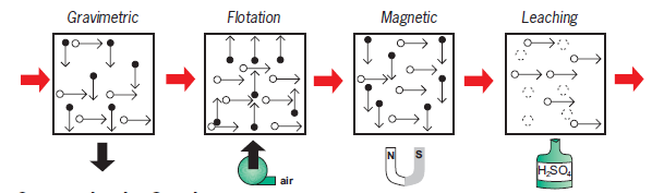


This article
describe the way of gravity separation.
Separation by Gravity
If there is a
certain difference in density between two minerals or rock fractions
they can be
separated by using this difference. Separation by gravity covers two
different
methods.
• Separation
in water (Gravity concentration)
• Separation
in a heavy medium (Dense Media Separation, DMS)
Separation in Water
Separation by Jigs
The jig
operation consists of two actions. One is the effect of hindered settling meaning that a heavier particle will settle
faster than a light particle. The other one
is the separation process in an upward flow of water which
will separate the particles by their density.
These two
actions are combined in a Jig by slurry pulses generated mechanically or by
air.
Coal Jigs (Baum type)
Suitable for
coarse load, feed size range maximum 175 - 200 mm (7 - 8 inch), minimum 40 - 60
mm (1.5 - 2.5 inch).
• Air
pulsation type
• Two
or three products
•
Automatic discharge
•
Modular design, bed area and elevators designed to suit duty.
•
Designed to handle high portions of sinks compared to the mineral jig.


Mineral Jig (Denver type)
Suitable for
minus 6 mm (3 mesh) feed, primarily a "through the bed" jig.
•
Simplex or duplex versions
•
Heavy-duty - long life diaphragm
•
Synchronized water valve
•
Variable stroke
•
Right or left hand arrangement
Operation
1. On the “forward
stroke” thefluidized particle bed reorganizes and
•
lighter particles move to a higher bed position
•
heavier particles move to a lower bed position

2. On the “back stroke”
the separation bed is resting (closed) and the heavy particles are drawn down
through the particle bed into the concentrate zone.
Separation by Spiral Concentrators
A spiral
concentrator uses gravity to separate particles of different densities. It should
not be confused with a Spiral Classifier which usually separates particles of
different size.
A Spiral
concentrator consists of one or more helical profiled troughs supported on a
central column. As slurry travels down the spiral high and low density
particles are stratified and separated with adjustable splitters at the end of
the spiral.

Spiral – applications
Anthracite, Coke
Breeze, Iron ore,Beach sand, Ferro chrome, Phosphates,
Carbon/grit,
Gold/carbon, Retile,Cassiterite, Gold sand (re-treatment) ,Soil washing,Coal,
Graphite, Zirconium
Separation by Shaking Tables
A cross stream
of water transports material over the table to riffles running perpendicular to
the direction of feed. Particles build up behind each riffle and stratification
occurs with heavier particles sinking to the bottom. The light particles are
carried over each riffle to the tailings zone. The shaking action of the tables
carries the heavy particles along the back of each riffle to the concentrate discharge.

Separation in Dense Media
Gravity
separation utilises the settling rate of different particles in water to make a
separation. Particle size, shape and density all affect the efficiency of the separation.
Dense Media Separation (DMS) takes place in
fluid media with a density between that of the light and heavy fractions that
are to be separated. The separation is dependent upon density only

Dense Media Separators
Drum Separator
Mainly mineral
applications Particle size range 6-200 mm (1/4” – 8”), Simple and robust, Low medium input, Max.
media density =3.5.

Dense Media Circuit

1. Feed
preparation screens(removal of fines)
2. DMS separator
(see below)
3. DMS screen
(drain and washing stages)
4. Dense media
circuit
DMS – Applications
Coal, Tin,Diamonds,
Manganese,Iron Ore, Phosphate,,Chromite Scrap metals,,Fluorspar
In many cases
Dense Media Separation is used for “Pre- concentration” e.g. rejecting waste
material prior to further processing (typical between crushing and grinding).
Dense Media Circuits – Sizing
These systems
have to be adapted to each particular case. For rough estimations the following
figures can be used.
1. Feed preparation screens
Screens to be of
horizontal vibrating type (“Low Head”) with width determined by particle size,
solids density and amount of fines. Use the following guide-lines for screens.
2. Medium feed rate
1.7 m3/t (450
USG/t) dry solids for drum separator systems,4.0 m3/t (1050 USG/t) dry solids
for DWP system.
3. Medium loss
For coarse feeds
(> 6 mm, 1/4") 100 g/ton solids,For
fine feeds (< 6 mm, 1/4") 150-300 g/
ton solids depending
on material porosity.
4. Magnetic separator
Magnetic
separator can be roughly sized from a figure of 3.5 m3 (900 USG) diluted medium
per ton feed solids.
5. Spray screens
The width of the
screens depends on the amount of spray water used (= feed to the magnetic
separator) and the sink/float distribution.
sinonine can also provide sand washing plant EPC.
sinonine can also provide sand washing plant EPC.


评论
发表评论